Dimensioning.
After preparing a sketch of any drawing, some information is to be written on it.
For example, the distance between different surfaces, the location of holes, number of holes, type of material, etc.
Such information is presented bylines, digits, symbols, and notes. The writing of measurement of such information is called Dimensioning.
By dimensions, the shape and size of an object are explained. A worker can complete the job according to the dimensioning.
If the size of an object is represented then such a measurement is called Size Dimension, Similarly, if the place of an object is represented then such a measurement is called Location Dimension.
If the dimension is written in the same direction in the whole drawing, then such a method is called Unidirectional Method.
If the dimension is written in two directions, then such a method is called Aligned Method.
In addition to this, if the dimension it is written parallel to the central line, then such a method is called Base Line Method.
The beauty of a drawing depends on the beauty of dimensioning.
Types of Dimensioning.
There are two types of writing dimensions on a drawing.
1. Size Dimension.
2. Location Dimension.
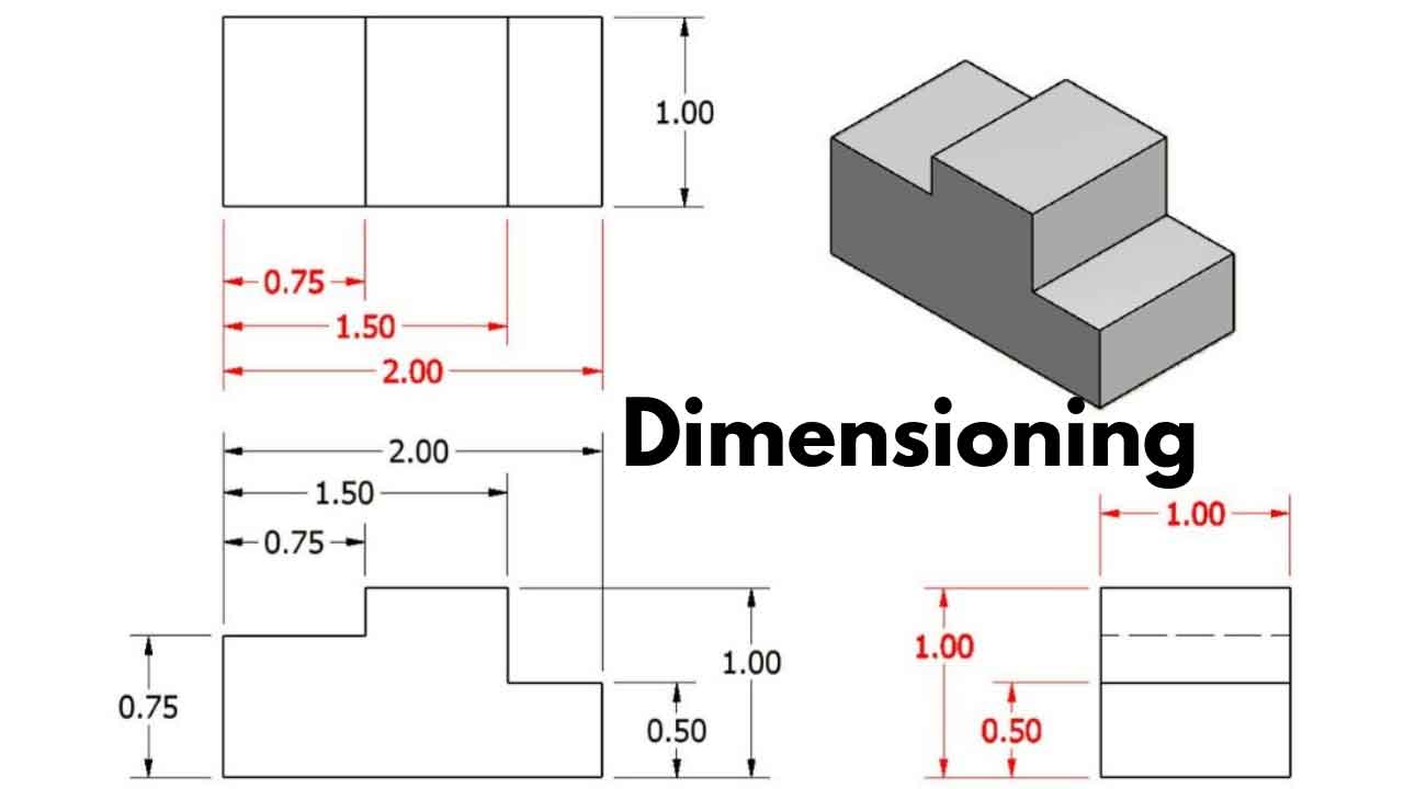
1. Size Dimension:
In this type of dimension, the external size of an object is represented. Also, the sizes of different parts of a drawing are shown there.
This shows the length, breadth, and height.
Such a dimensioning is represented mostly by the front view.
2. Location Dimension:
In this type of dimensioning, the distances between different parts of the object and the distances between the centers of circles are shown.
In addition to this, the distance of the center of a circle or that of any other part from some particular point is represented.
Location dimension is divided into three different ways:
1. Center to Center Distance.
2. Center to Surface Distance.
3. Surface to Surface Distance.
Order of Dimensioning.
After completing a drawing, the following order is to be kept in mind.
This makes a drawing beautiful. It also saves time.
1. Drawing of Extension Line.
2. Drawing of Dimension Line.
3. Drawing of Arrow Heads.
4. Writing of Numerical Value.
5. Drawing of Cutting Plane Line.
6. Drawing of Leader Line.
7. Drawing of Center Line.
Systems of Dimensioning.
The following are the three systems of writing dimension.
1. Unidirectional Method.
2. Aligned Method.
3. Base Line Method.
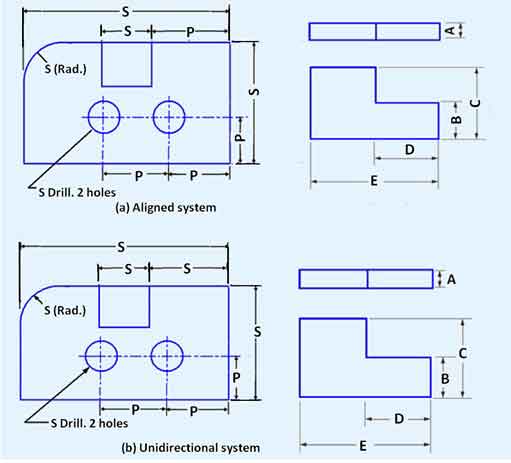
1. Unidirectional Method:
This method is mostly used in dimensioning. In this method, the whole dimension is written in the same direction in the whole drawing.
This direction is generally vertical.
2. Aligned Method:
In this method of dimensioning, it is written in two directions in the whole drawing.
It is written upward and on the right side and is read from the bottom and right side of a drawing.
Its advantage is that the dimensions can be written in the horizontal direction which is very easy to write.
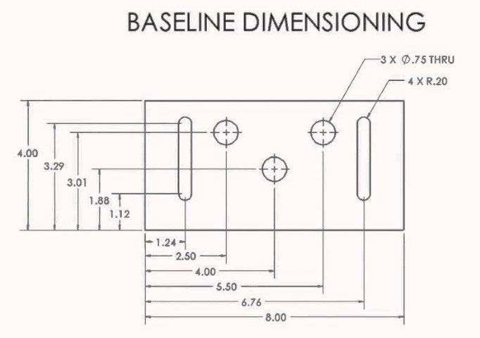
3. Base Line Method:
In this method of dimensioning, baseline is used to write the dimension of various parts of a drawing. Then all the dimensions are written parallel to the base line.
In writing dimension, the smallest one is written to the side of the object, and the biggest one is written on the external side of the object.
All other dimensions are written in between them.
In this system, the chances of mistake are very rare.
Elements of Dimensioning.
For any drawing to be workable, it is necessary that all the needful dimensions should be written on it, so that all information could be used properly.
For this purpose, the following elements are written down.
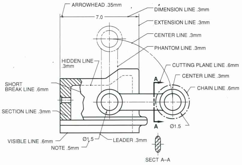
1. Dimension Line.
2. Extension Line.
3. Center Line.
4. Leader Line.
5. Arrow Head.
6. Numbers.
1. Dimension Line:
A Dimension Line is drawn for a given dimension of an object. This line should be at a distance from 10 mm to 15 mm from the object line.
For writing a dimension, this line is broken from the middle, and the dimension is written in the middle space. Alternatively, the dimension is written on it after its completion.
2H or 4H pencil is used for this purpose.
2. Extension Line:
Such lines which are drawn extending from the ends of a part of a drawing so that the dimension can be written in between them are called extension lines.
2H or 4H pencil is used for this purpose.
There should be a distance of 1 mm between them and the object line.
3. Center Line:
Such a line is used to represent the center of a cylindrical part of a drawing.
For example, a hole shaft, etc.
This should be extended up to 1 mm distance from the object line.
4. Leader Line:
Any note or specification is written on an object with the help of this line. This is drawn with 2H or 4H Pencil.
It consists of a circle and a leader.
5. Arrow Head:
This is used at the ends of a dimension and the end of a leader. The length of the arrow-head used in engineering drawing 3 mm.
6. Numbers:
After the completion of any geometric shape of an object, the writing of its size is desired.
Numbers are used for this purpose. The height of the number is kept 3 mm.
Principles of Dimensioning.
After completing a drawing, it is necessary that its measurements and notes should be written in such a way that they can be read easily.
Follow are the Principles that have been devised for this purpose.
1. The dimensions should be given on such view which illustrates the true shape and size of an object.
2. As far as possible the dimensions should be given outside a view but can be given inside as well if unavoidable.
3. All the dimensions are given in group form. Scattering of these is not correct.
4. The dimensions should be intelligibly written.
5. All the dimensions should be written parallel to the object line and the numbers should be written such that they could be read easily.
6. The dimensions should not be repeated unless necessary.
7. The unnecessary dimensions should be avoided.
8. The extension and dimension lines should not intersect in any case.
9. While giving dimension after completing a drawing, it should be kept in mind that no unit should be written with any number.
10. The numbers should be clear, legible, and intelligible.
11. The circle, arcs, and wholes should be compatible with their radius of diameter.
12. If dimensions are needed to be given in concentric circles, then try to make them on the front view and then write their dimensions.
13. The Leader Line should be used for writing dimensions of the circles which should illustrate their diameters.
14. Refrain from ambiguous and complicated dimensions.